The Star Base is finished, it took some time but now it is done. And as usual, especially with such a large project, the real things looks different in some areas compared to the digital model. In case of the Star Base this was partially true due to a design error in the digital model, resulting in a missing radar disk, some issues with the final look and also sometimes due to missing or wrongly ordered parts.
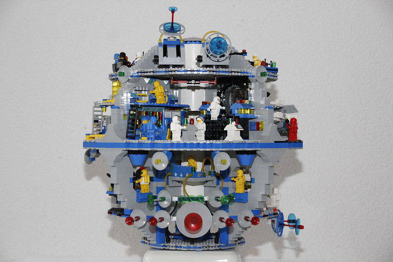
But enough words, here is the Star Base in all its glory:


As a reminder, in case you have not seen the post of the digital model, here is the list of the different section of the Star Base
- On the lowest deck a storage room
- A Helio-Physics laboratory on the first deck
- A hanger for the SunHopper
- The Main Reactor
- One controllable antenna
- The large antenna array
- Crew accommodation with sleeping berths, lockers, lounge, …
- Main antenna with control computer
- A hanger for the NeutronJet
- Central operations
- Controllable Helio-Physics Antennas
- Droid-Repair Workshop
- Meeting room
- Control room for the main antenna
Here is now a closer look and description of the model and each of its decks. In a separate post, I will just put the different pictures, the renderings from Stud.IO and the real model next to each other, with some comments on the differences.
Lower Deck

The Power deck is identisch to the digital design and we see one of the mechanics looking for parts

Here is the digital design,.
1st Floor Deck
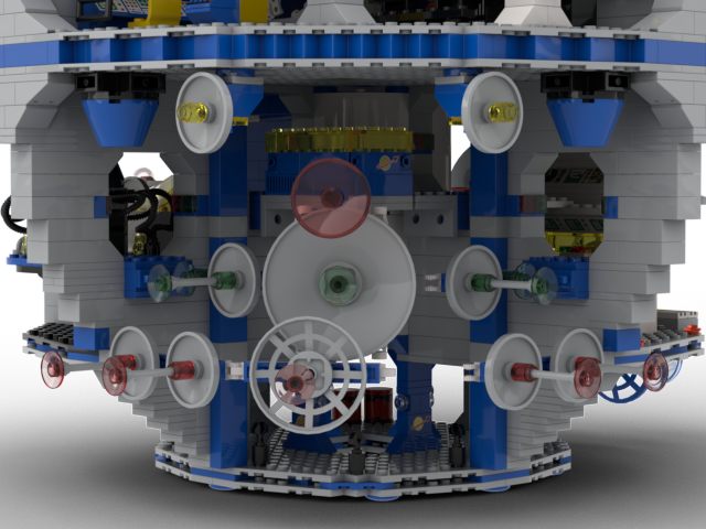
The large antenna deck consists of two antenna strips and some smaller steerable side antennas. The antenna array is mainly used to record the gravitational waves of the neutron star. This is especially intended to record physical processes inside RX J1856. in potential combination with other antennas of the StarBase, which measure in different wavelength of the spectrum, the science team is getting every day a better understanding of RX J1856.
Antenna control and calibration is performed by high-performance computers from the platform in the rear deck area. The elaborate and dedicated control by some computer system is necessary to detect the slightest fluctuations in the space-time continuum.
The analysis of the date is done in the Helio-Physics Lab.

In the real world design the antenna deck was modified quite a bit. The large center antenna above did not work when I made the connection of the bars. The dish was too large and would not fit with the lower dish. So the center section had to be redesigned to have sufficient space for the large middle dish. I also had to change the control station in the background. The design did not allow for playability, meaning it was not possible to put the astronaut in place. And I had to lower the cable connectors (1×1 bricks with side studs) on the station as otherwise I could not connect them to the antennas

The Helio-Physics Lab runs the various simulation and result analysis coming in from the antenna array.
It allows to analyse samples from the residual material of the supernova forming the neutron star. The samples are collect by the SunHopper and powerful mass spectrometers in the Helio-Physics Lab can break them down on atom level and provide a complete history of the elements. And it seems, the dust in the NeutronStar System contains valuable materials that can be harvest.

The real world design of the Helio-Physics lab was hardly changed. The only modification was actually linked to the two blue antennas. The location shown in the digital design did not work as the antennas couldn’t actually rotate. Thus I moved them to the location shown on the picture. A minor change was linked to the color of the computer panels, I had troubles to buy sufficient white panels for a decent price. So I bought also some yellow panels that you see used here. I also replace the yellow antennas for the scan dishes with solid white ones. Trans-yellow antennas are incredible expensive, so I decide to go with the cheaper white ones.
And first simulation done in the Helio-Physics lab show, that the Neutronstar can be harvested for energy. Thus a mining space station, collecting the dust and small debris still floating through system and processing it, could become reality.

As you can, the actual build stayed identical to the digital model.

The main reactor supplies the space station with energy. Since there is no easy way to use the neutron star for energy generation at the moment, the space station is supplied with energy by a fusion reactor. The reactors of the latest generation are quite compact and require little maintenance. Therefore the reactor can be monitored and controlled from the control room.

Also the main reactor was not modified compared to the digital mode. And the loose connector actually provides the reason for technician to be there.

In order to better investigate the Neutron Star, a SunHopper is also operating from the StarBase. The SunHopper has a dedicated hanger, that allows repairs and re-fueling. The rotating platform allows to access the SunHopper resp makes it easy for it to land and start. The approach to hanger is controlled by the two approach radars (grey dish with green transmitters) as of course a collision would have a devastating effect this far away from home. When the SunHopper has collected samples, they can immediately be transported to HelioPhysics Lab next door for analysis. The missions are in principle controlled from the main control room.

The real construction for the SunHopper hangar sticks to the original – approach antennas, traffic lights, fuel station and turntable, all as digitally planned.
What is clear is that the platform cannot rotate with the SunHopper on board if astronauts are also present. That’s caused bythe engine that sticks out. But the hangar is a very nice play feature, I like it a lot.

The smaller steerable antenna is a SAR radar for studying the various asteroids in the star system. The SAR provides a high-resolution image of the object being studied. The antenna can also be switched to a surface penetrating mode to provide information about the internal structure of the asteroids. Thus, it helps to identify possible exploitation targets for asteroid mining missions.

The actual build had to be changed because the 10×10 dish was needed for the helio-physics antenna. Since I didn’t want to buy new dishes (none were available in Switzerland and I wasn’t going to pay 10€ shipping for a 3€ part), I decided to work with what spare parts I had. This ended up with a smaller dish design, but a more layered approach consisting of multiple dishes of different sizes. This better reflects the different modes of operation of this Asteriod antenna.
Another change I had to make was the removal of the white dishes on the side. They were too big and the antenna could not move up and down because they were blocked by the computer. And another small change is the yellow color for the computer panels. The printed tiles in blue were hard to get (and expensive), so I replaced some of the blue tiles with yellow ones.
2nd Floor
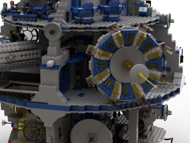
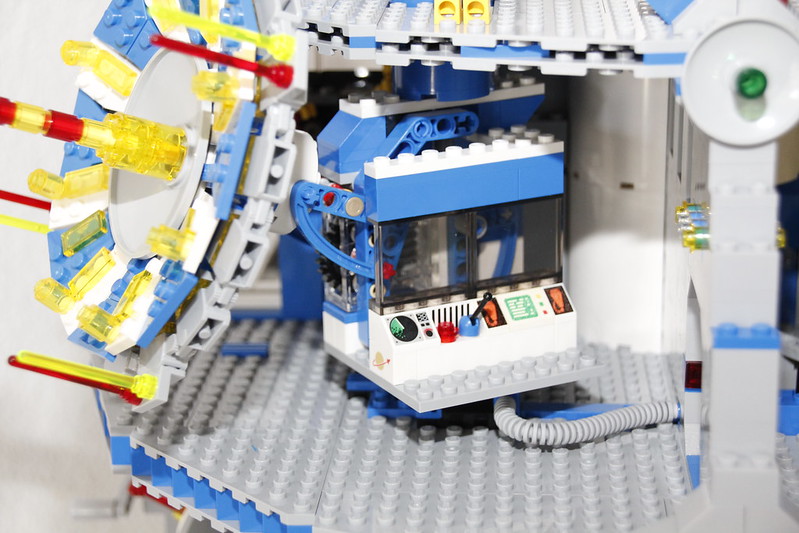
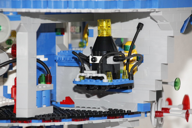
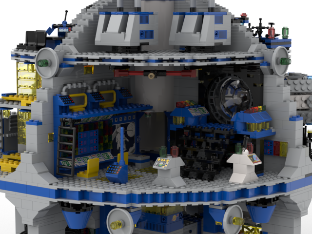
The heiko-physics antenna is the main instrument of the StarBase and is used to study the neutron star. The antenna allows to scan the star in different frequency ranges. At the same time the main antenna is also an active instrument, which irradiates the star with different frequencies and analyzes the corresponding echoes. Due to the size and the various subapertures the main antenna achieves a resolution over a huge spectrum never reached before.

Two changes were made to the helio-physics antenna, one is not visible in the pictures and was actually a digital design flaw. I overlooked a large dish on the back side. And that caused a whole chain of changes. The missing dish was a 10×10 dish and since I only bought the exact number of 10×10 dishes according to the digital model, I had to take it away from somewhere else, that was the SAR antenna on the 1st floor deck, so I had to change that too.
The other change is the number of side rod antennas, which I cut in half. This was caused by the lack of parts, for some reason I didn’t buy enough of these 2×2 panels/brackets. And the trans-yellow antennas are neon-green for price reasons. These used trans-yellow antennas are very expensive ….
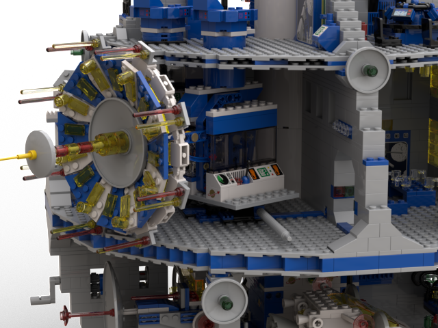
However, the various subaperatures, receivers and transmitters must be synchronized with each other in a complex way. This is done by special computers located directly behind the antenna to minimise the signals delays and to controls them without any loss of time.
The antenna controls are located in the deck above the antenna.
The measurement results are recorded and evaluated in the main control center.

Otherwise the rest of the room is as designed. And looks very nice. A small change was the light bar above the door. In the digital design it as all trans-clear, for the real design I went in the end with trans-yellow / trans-clear combination.
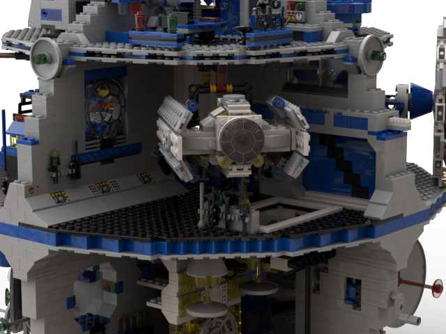
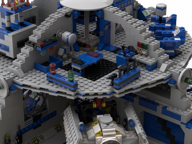
In addition to the SunHopper the NeutronJet was built. Thanks to its special shape and construction the NeutronJet can fly much closer to the neutron star than the SunHopper. However, as a result it is usually exposed to high levels of radiation and has to be decontaminated at great expense. The crane ensures that the ground etc. is not further contaminated. The floor hatch allows to analyze any samples directly in the Helio-Lab.

The NeutronJet hanger could almost stay identical. The only element I had to change was to place the tool storage more to the right side of the loading bay. At the original location seen in the digital design it blocked actually the rotation of the spaceship in the crane. Otherwise the rest worked as planed, also the NeutronJet stayed as digitally designed.
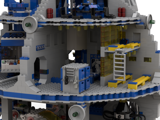
The crew’s bedrooms and lounges are kept quite simple. There are some beds to sleep on, a table for eating and compartments for personal belongings. The large monitor keeps the crew up to date during their breaks. The base runs in a 2-shift operation, i.e. 12 hours of waking and 12 hours of sleeping. The beds are shared, but are self-cleaning, so that everyone always slips into a freshly made bed. The lounge also has a direct slide to the hanger of the SunClipper, just in case you need to get up quickly

The crew quarters stayed almost identical with one exception, the large 1x6x5 brick in blue with the print on it. I had planned to use several of those however they have also shown to be very expensive and difficult to find. So I decide to go a very different path and actually use stickers! So I replaced them with grey 1x6x5 bricks, which are much cheaper and actually found square 45mmx45mm printable labels. So I designed my own stickers that I applied to the brick. In case of the crew quarter, it is one of the spaceships on mission, providing the Star Base crew with up-to-date information on a relevant mission while they take a break

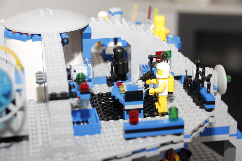
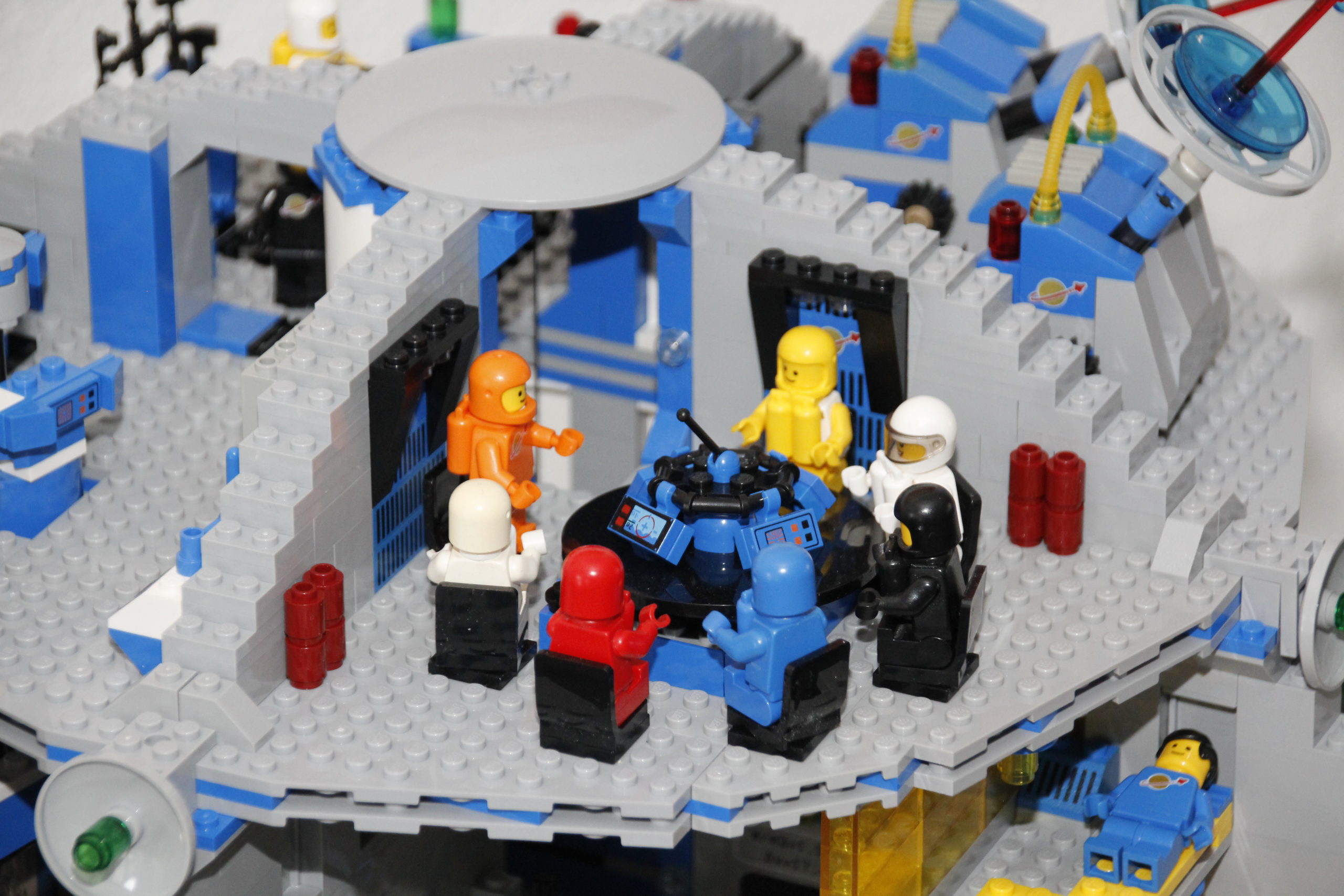
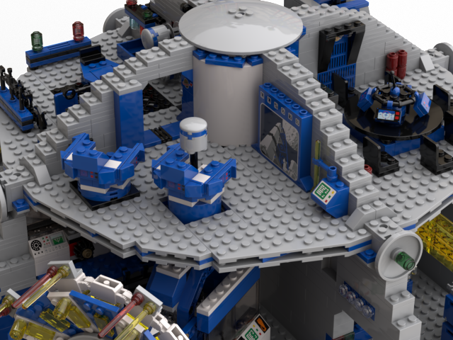
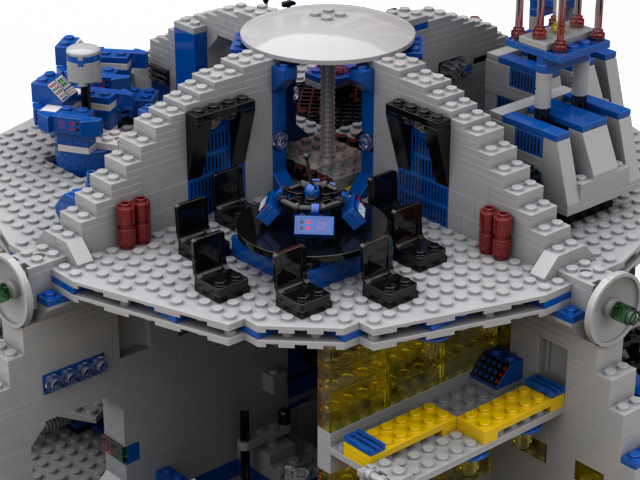
The two main scientific instruments, the two antennas, as well as the other operations of the space station are controlled and coordinated from the control center. The large computer wall is mainly used for the control and data evaluation of the two large antennas. The individual small consoles are mainly used for monitoring the station. The space ship missions and the hangars are controlled from the gallery, with a direct view of one of the hangars.

The control station also had only minor changes applied. Some of the blue computer tiles where replaced by yellow ones, for the reasons explained before. And of course also here I replace the printed 1x6x5 brick in blue with a grey version and a sticker. Here the sticker shows an image of the Star Base together with some curves, thus being clearly the main screen for displaying information about the station’s status. I also exchanged the computers on the upper deck aas well as the blue standalone terminal. I turned out that the blue slopes with the dot print is also an expensive and hard to get part, so I switched to normal computer set-up. Does not make a difference and saves a lot of money.

Uppderdeck
The antenna control is located above the main antenna. This is where the technicians are located who then align the main antenna under the guidance of the scientists from the control center. This, in turn, must be precisely coordinated with the synchronization computers of the main antenna, as otherwise there may be severe interference in the antenna system.

The antenna control room also went through some changes. While nothing major in terms of design, some computer station colours where changed. The replacement of blue computer panels with white tiles was driven by the fact mentioned before. Blue tiles are simply more expensive and less available than while and yellow, so I replace some with white tiles. And in order to get a better matching color scheme in terms of blue / white combination I also replaced the slopes with whites one (and I took the radar print). And another reason was, that by the time I came to this deck, I ran out of blue computer stations.
And also here, I replaced the blue 1x6x5 brick with a grey one and a sticker, here showing the star under observation. Fits actually better than the original printed blue brick foreseen.
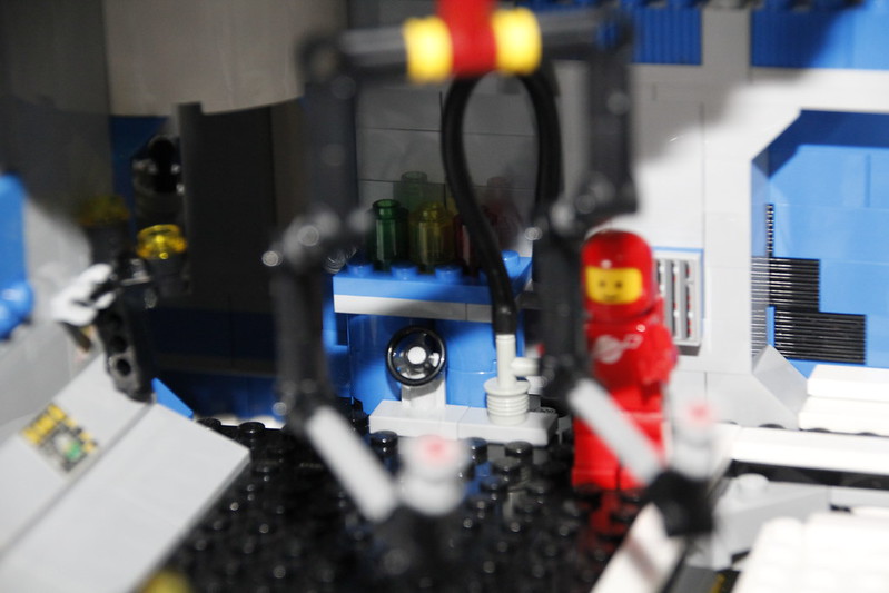
The workshop mainly repairs the robots used in the base and on the space ship missions. Because of the hard radiation near the neutron star the robots fail again and again. But also possible repairs of devices, computers or other equipment are done here.

The workshop stayed true to its digital design, the only small change as the color scheme on the mouse robot, where i missed grey slopes and replaced them with blue ones. Otherwise it was build as designed.
In the conference room, the daily situation meetings take place, but also shift handovers or mission planning. The scientists also meet here to discuss their results and plan further research.

Also the conference room stayed almost true to is digital design. I moved the 1×2 bricks with the space logo one row down, so it is better visible. Otherwise no change. And as they are all together here is the color code for the crew:
- Orange: Boss
- White: HelioPhysics
- Red: Flight Maintenance
- Blue: Station Operations
- Black: Who knows
- White ESA: Lead Scientists
- Yellow/White: Technicians
- Yellow: Science Operations (not invited for this meeting)
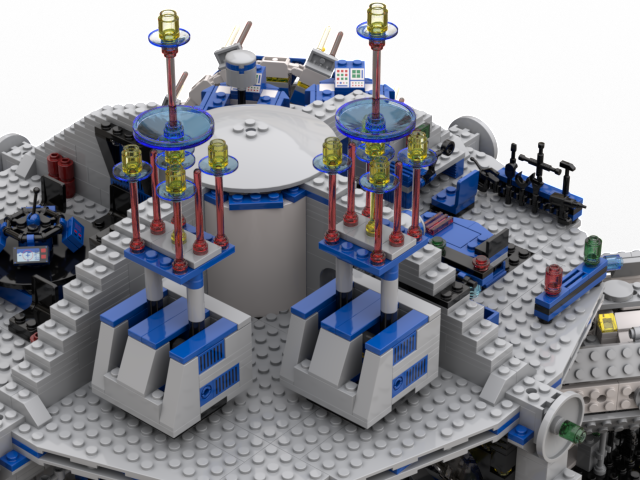
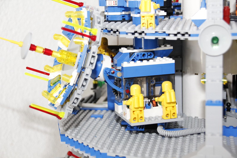
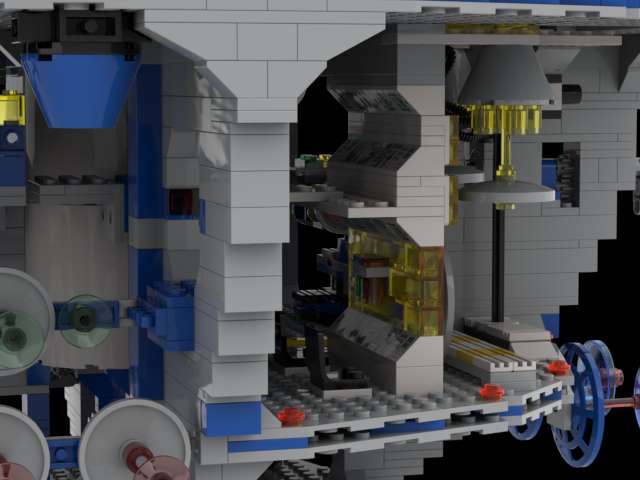
The second large antenna system is the steerable Helio-Physics antenna consisting of two sub-antennas. The antennas are directed synchronously at the object and then fire a series of pulses of different frequencies to analyze the echoes accordingly. Sometimes the main antenna or the antenna array is also used as an additional receiver. Depending on the procedure, measurements can take seconds, hours or even days. The antennas are also controlled from the control center.

This section was changed the most. The antenna design did not really look great in the real word. And together with the initial design of the turrets, looked much more like the Star Wars Guns than a Star Base antenna system. In addition I had not sufficient 1×2 bricks with grill pattern, so I also had to improvise on this part. For the antennas I went with a much for classic design with dishes, also hear applying the stacked dish approach, keeping the trans-blue dishes as a design element. I also reduced the length, having the antennas less stick out. This already helped to remove the “gun” look. In addition I put slopes on the turrets and together with the yellow hose it got much more an antenna base feeling to it compared to the previous design.
This was clearly an example where the look /impression of the real world was not “captured” by the digital design and what looked good on the screen did not look good in real life.
So that was the detailed comparison of digital and real world design, I personally think the Star Base is a great model and I hope that I can actually exhibit it at the Steinchenwelt 2021 this year. And if you want to see a few more pictures here we go: